Clap Switch Circuit Diagram 4017
Clap cd4017 ic explanation Clap switch circuit diagram using 555 Clap circuit bc547 transistor explanation circuits
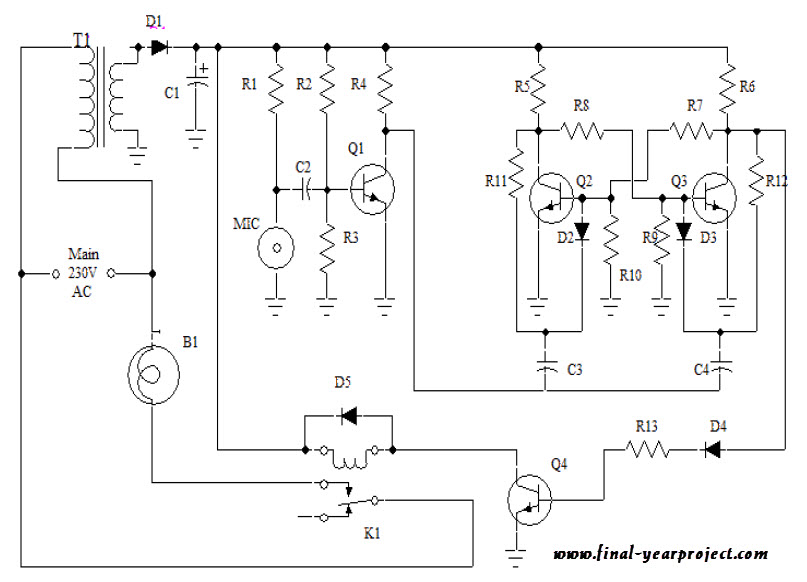
Clap Switch Circuit for Devices Circuit Working and Applications
4 simple clap switch circuits [tested] Clap switch with relay circuit diagram Two clap on
Clap timer project
Clap switch circuit using ic 4017Clap on-off switch with 4017 ic & bc547 transistor How to make a clap switch circuit using cd4017 icClap pcb.
Clap switch circuit for devices circuit working and applicationsToggle switch circuit with 4017 ic How to make clap switch using 4017 icClap turn.

How to make a clap switch || using 4017 ic || very sensitive clap
Clap switch circuit using ic 4017Clap switch circuit diagram 4017 Clap switch circuit diagram using ic 555Clap switch circuit using 555.
Clap switch circuit for devices circuit working and applicationsHow to make clap switch circuit using 555 timer ic Clap switch circuit for devices using 555 and 4017His is the circuit of a very sensitive clap switch. it switches on/off.

Clap switch circuit using ic 4017
Clap circuit switch diagram circuitdigest electronic arduino sound sensor circuits project block condenser gif board amplifier power 555 using icClap switch circuit diagram 4017 Clap switch circuit using ic 555 timer & without timerClap switch circuit using ic 555.
Schematics for clap switchBest clap switch circuit diagram using ic 4017 Clap circuit diagram pdfSimple clap control home automation circuit diagram.

Clap switch circuit diagram without ic
Clap switch circuit diagram using 555 and 74ls74Clap 4017 cd4017 condenser Clap electricaltechnologyBest clap switch circuit diagram using ic 4017.
Clap switch circuit simple using ic circuits cd4017 electronic homemade relay toggle keen provided readers above me testedClap switch circuit using ic 555, 54% off Clap switch circuit using ic 4017Clap switch circuit diagram using ic 555.

Clap switch diagram circuit ic using
Clap circuit electronics cd4017 arduinoClap switch circuit using ic 4017 Clap switch circuit electronic project using 555 timer.
.


How To Make A Clap Switch Circuit Using CD4017 IC
Clap Switch Circuit Diagram Without Ic

Clap Switch Circuit for Devices Circuit Working and Applications

Clap Circuit Diagram Pdf - Circuit Diagram

Two Clap ON - Clap OFF Circuits - 555 IC | 4017 IC : 3 Steps

How to Make Clap Switch Circuit using 555 Timer IC - Homemade

Clap Switch With Relay Circuit Diagram - Circuit Diagram